Oil Seals

Trusted China Oil Seal Manufacturer for Reliable Sealing Solutions

Savvy supports fast and flexible oil seal supply with over 5,000 molds available to cover a wide range of sizes and specifications. Standard oil seals are kept in stock for immediate shipment, ensuring short lead times for both urgent and bulk orders. With established logistics partnerships, we offer reliable global delivery and competitive shipping costs to meet your business needs.

Oil Seal Overview

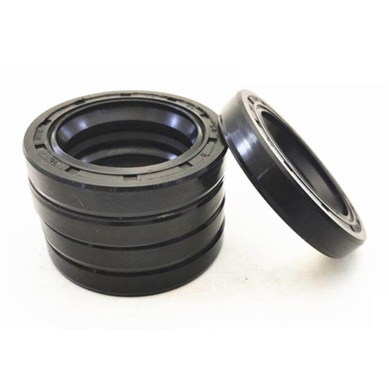
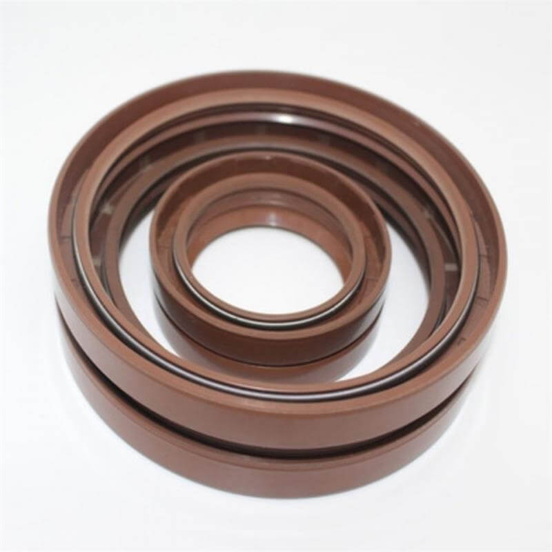
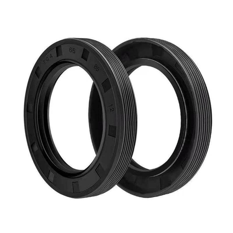
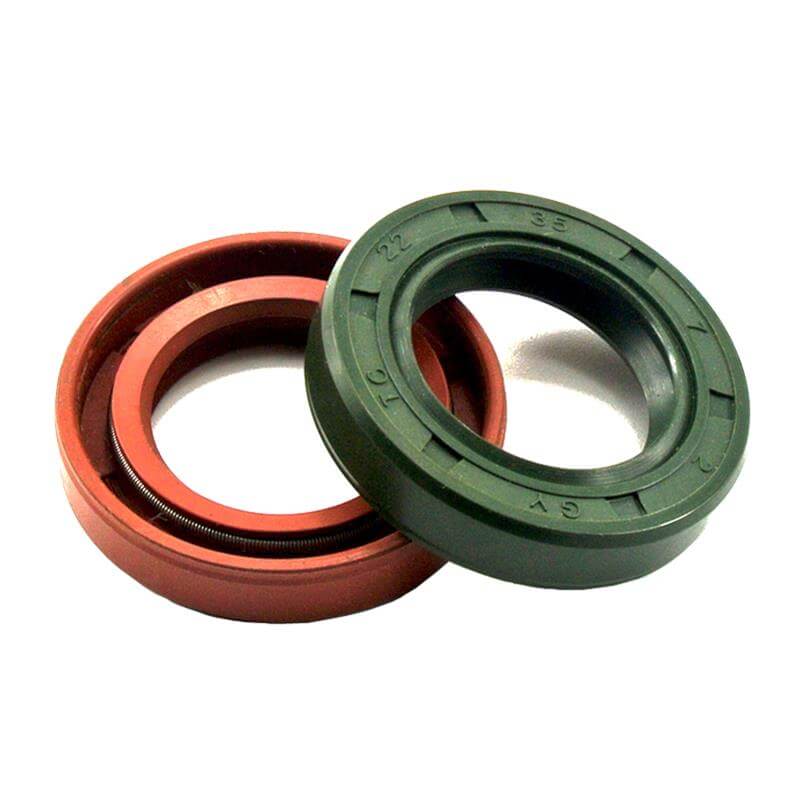
An oil seal is a precision mechanical component designed to retain lubricants such as oil and grease within rotating machinery while blocking external contaminants like dust, dirt, and moisture. It forms a dynamic sealing interface between the rotating shaft and the stationary housing, helping to minimize leakage and protect internal components.

By effectively isolating lubricated areas from the external environment, oil seals help reduce wear, prevent contamination, and extend equipment service life, ultimately lowering maintenance needs and downtime.

In the industry, oil seals are also known as Lip Seals, Rotary Shaft Seals, or Radial Shaft Seals. For more specialized engineering specifications and high-performance technical data, please explore our dedicated Rotary Shaft Seals page.

Oil Seal Structure & Profile

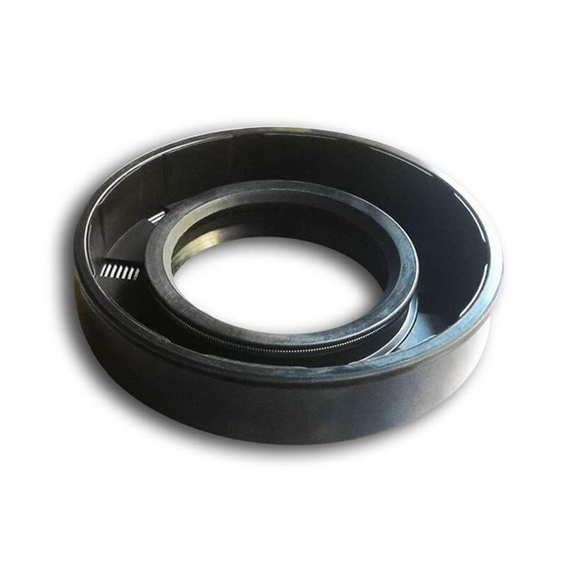
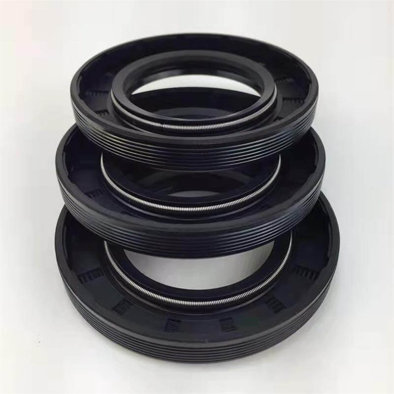
The structure of a standard oil seal combines mechanical stability with flexible sealing. It is primarily composed of three key elements: the Metal Case, the Rubber Element, and the Garter Spring.

  1. Metal Case (Metal Insert/Skeleton): This provides the structural rigidity needed to hold the seal in place within the housing and maintain its shape under pressure.
  2. Rubber Element: Molded around the metal case, the rubber element provides both dynamic and static sealing. It consists of three primary sections:
    • Rubber Body: This is the rubber layer covering the metal skeleton. It ensures a leak-proof static seal between the oil seal and the housing bore, while also protecting the metal case from corrosion.
    • Primary Lip (Main Sealing Lip): This is the most critical component. It maintains direct contact with the rotating shaft to provide a dynamic seal and prevent lubricant leakage.
    • Dust Lip (Secondary/Auxiliary Lip): This is a springless auxiliary lip that acts as a barrier against dust, dirt, moisture, and other external contaminants to protect the main lip.
  3. Garter Spring (Optional): Many seals use a garter spring to maintain constant tension, but some designs rely on the rubber’s elasticity for a “self-tightening” effect without a spring.

The image below shows the detailed structure and profile of the oil seal, including the main components and other important parts.

Oil Seal Types

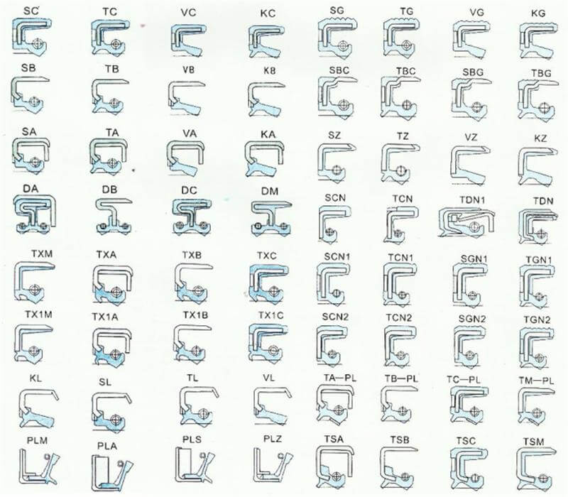
Oil seals are classified by their structure, casing, lip type, and spring use. Common types include TC, TB, TA, SC, SB, SA, KC, KB, KA, VC, VB, and others. Each type is built for different working conditions, pressure levels, and durability needs. The TC skeleton oil seal is the most common standard type for general applications. We produce this main type, as well as other popular designs, to meet your various sealing needs.

Oil Seal Sizes

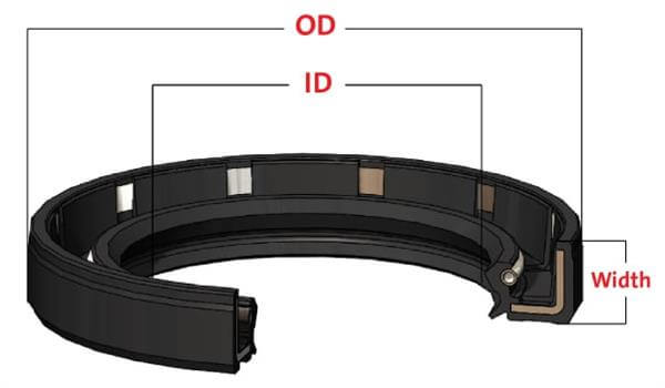
oil-seal-ID-OD-widthAn oil seal is defined by three core nominal dimensions: ID (Inside Diameter), OD (Outside Diameter), and W (Width). Standard sizes are typically expressed as ID x OD x W (e.g., 20 x 30 x 7 mm). These nominal values are designed to match the machined shaft and housing bore dimensions, NOT the oil seal’s actual physical dimensions. The seal’s inner lip is slightly smaller for a tight fit on the shaft, while its outer diameter is slightly larger to ensure a secure press-fit in the bore.

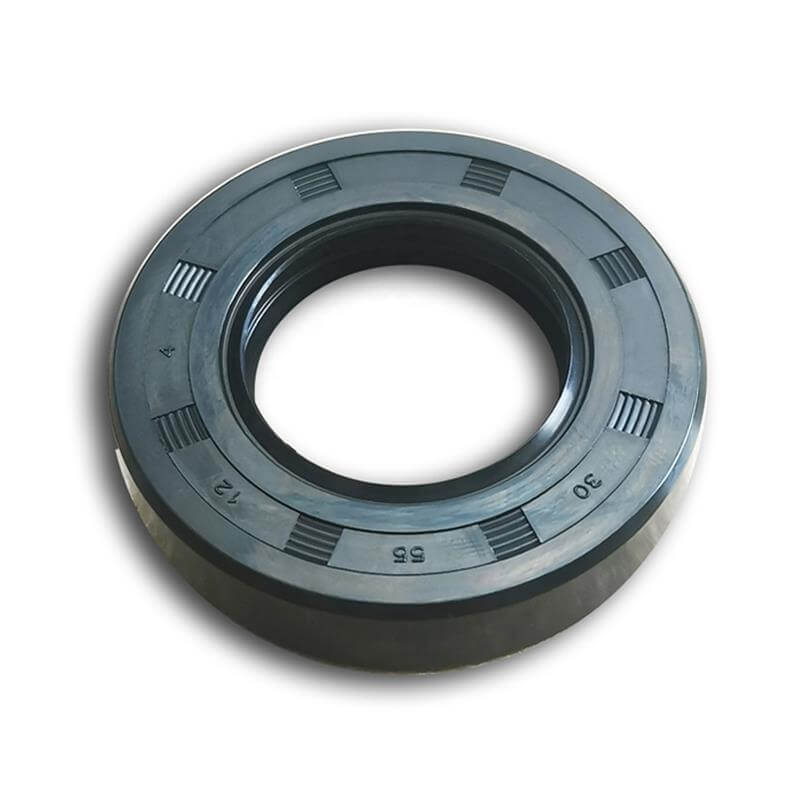
Whether metric or inch-sized, most oil seals have their specifications marked directly on the outer casing. Metric seals often display dimensions numerically (e.g., “20 30 7” for 20mm ID, 30mm OD, 7mm Width), while inch-sized seals may use decimal values or standard part codes. These markings provide a quick reference to help minimize errors during identification and ordering.

Note: Width is sometimes referred to as H (Height) or T (Thickness) by some users, but W is the standard term.

Oil Seal Materials

An oil seal consists of a metal case, a garter spring, and a rubber element. The materials for the metal case and garter spring are typically standard: carbon steel (grades Q235, A36, or S235JR) is used for the case, while spring steel (such as 65Mn, 1065, or C67E) is used for the spring in general applications. For special requirements, stainless steel is available for both cases and springs to ensure superior corrosion resistance. Grade 304 (SUS304 / 1.4301) is the standard choice, while Grade 316/316L (SUS316 / 1.4401) is offered for highly corrosive environments.

The rubber compound is often the critical performance factor. Selecting the right rubber is essential because oil seal lips must withstand continuous rotation, friction, and specific fluids. While NBR and FKM cover most industrial applications, specialized needs often require ACM, VMQ, or PTFE.

NBR (Nitrile) is the industry standard for general-purpose sealing across countless machines with the most competitive pricing. It offers the best balance of wear resistance and cost for petroleum-based oils and greases up to 120°C.

FKM (FPM/Viton) is much more expensive than NBR but is the premium choice for harsh environments with high heat or chemical exposure. It handles temperatures over 200°C and resists aggressive fuels and synthetic lubricants where NBR would harden or degrade prematurely.

ACM (Acrylic) is a cost-effective alternative to FKM, particularly for automotive transmissions. It provides reliable heat resistance up to 150°C in hot gear oils without the high price tag of fluorocarbon rubber.

Silicone (VMQ) excels in extreme cold and heat, ranging from -50 °C to 220°C, and offers excellent flexibility. Due to lower tear strength, it is best suited for low-speed, food-grade, or medical applications rather than high-pressure rotary sealing.

PTFE (Teflon) seals are non-rubber solutions designed for the most extreme operating conditions. They offer near-zero friction for dry running, very high speeds, or corrosive media that would quickly destroy standard elastomers.

The chart below visualizes the maximum safe surface speed for each elastomer. Exceeding these limits generates excessive heat, causing the rubber to harden or crack. Use this guide to match your shaft diameter and RPM with the optimal material.

Shaft RPM, Surface Speed & Material
MaterialSpeed Range & Performance
NBRLow to Medium Speeds
(Surface Speed < 12 m/s)
ACMMedium to High Speeds
(Surface Speed < 20 m/s)
SI/FPMHigh Speeds
(Surface Speed > 20 m/s, up to 35+ m/s)
How to use this chart:
1. Locate your Shaft Diameter on the bottom axis.
2. Follow the vertical line up to your operating RPM curve.
3. Check the Surface Speed on the left axis or identify the Material Zone where the point falls.

Oil Seal Hardness

Unlike O-rings, which are available in a wide range of hardness levels, oil seals maintain a relatively consistent hardness. This is because the metal case provides structural support, while an internal garter spring generates the necessary radial sealing pressure. Consequently, the rubber lip requires only standard flexibility to maintain contact with the shaft and resist wear, rather than specific hardness to resist compression.

Hardness applies solely to the elastomeric component and is measured on the Shore A scale. For standard applications, materials like NBR, FKM, VMQ, and ACM typically default to 70-75 Shore A, while high-pressure variants reach 80-85 Shore A. These values represent decades of industry optimization for the metal-spring-lip system.

As these are established industry norms, hardness is not marked on the seal body. Customers simply need to select the correct material and size; the optimal hardness is engineered by default. Custom hardness is available only for specialized applications.

Oil Seal Colors

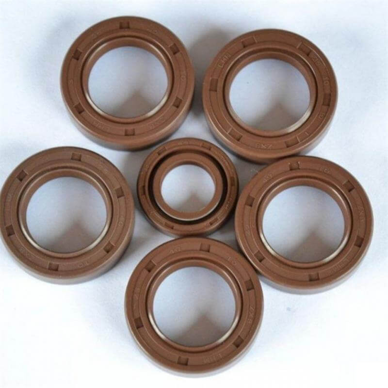
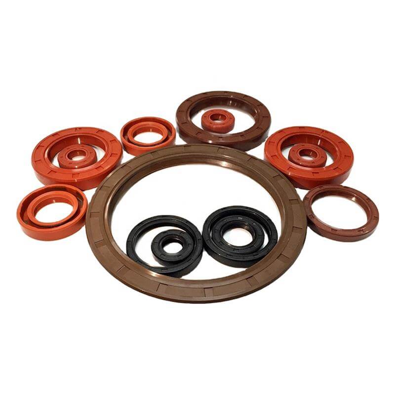
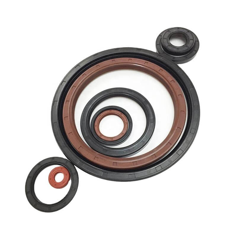
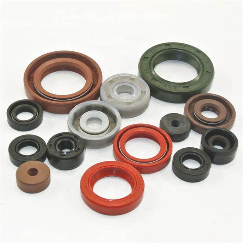
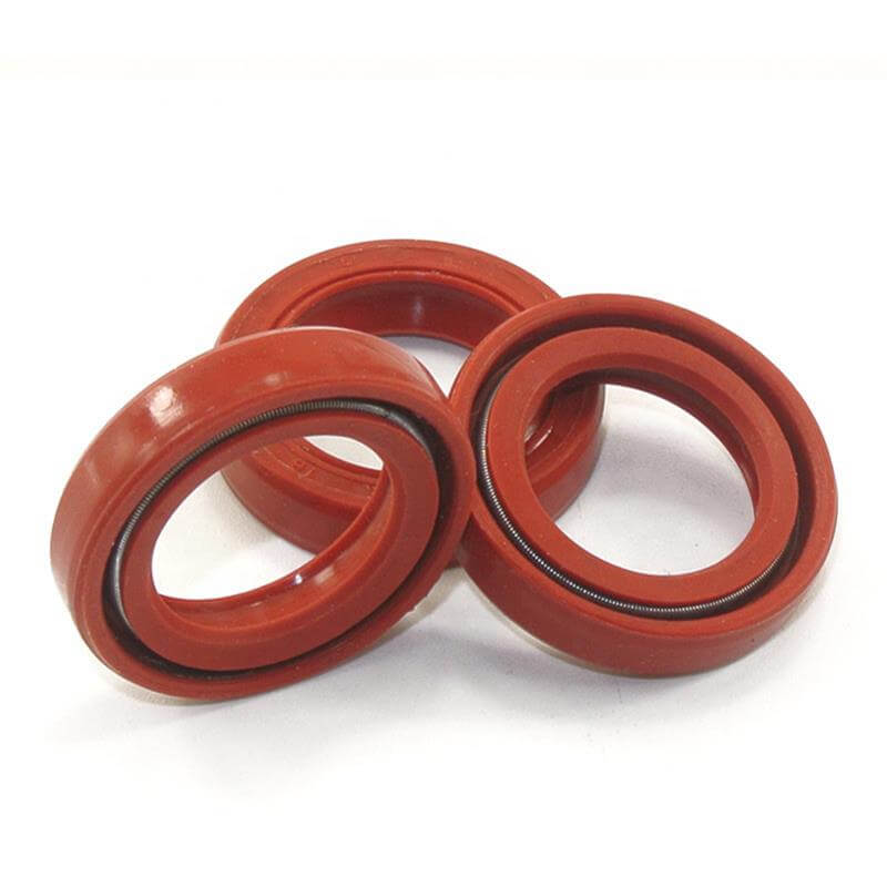
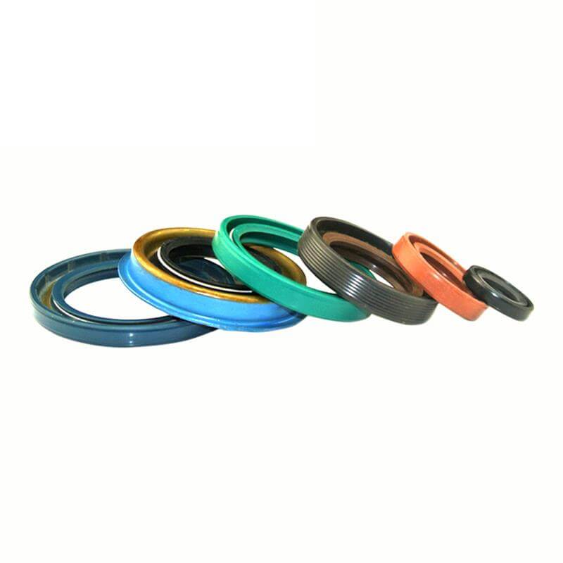
Oil seal colors typically follow industry-standard conventions for easy material identification. NBR (Nitrile) seals are most commonly black, FKM (Viton) seals are brown, Silicone (VMQ) seals are red, ACM (Acrylic) seals are black or dark blue, and PTFE (Teflon) seals are white. These standard colors help technicians quickly recognize material properties during installation and maintenance, while also keeping production costs and delivery efficient.

We can also customize oil seal colors to meet specific project or branding needs. Customers only need to provide a standard RAL or Pantone color number, and we will adjust the rubber compound accordingly. Please note that custom non-standard colors will generally result in higher costs, a larger minimum order quantity (MOQ), and longer production lead times.

Oil Seal Tolerance

To ensure superior sealing performance and long-term reliability, our oil seals are manufactured in strict accordance with international standards, including ISO 6194-1, DIN 3760, and GB/T 13871.1.

The following tolerance tables provide essential data for the nominal Lip Inside Diameter (ID), Outside Diameter (OD), and Width (W), as well as recommended machining tolerances for shafts and housing bores. These precise parameters are critical for achieving an optimal interference fit and preventing leakage in demanding industrial applications.

Oil Seal Lip ID Interference & Tolerance (mm)
Shaft Diameter (d1) Primary Lip Dust Lip
Interference Limit Deviation Interference Limit Deviation
Up to 30 0.70 – 1.00 +0.20 / -0.30 0.30 ±0.15
30.01 – 60 1.00 – 1.20 +0.20 / -0.60 0.40 ±0.20
60.01 – 80 1.20 – 1.40 +0.20 / -0.60 0.50 ±0.25
80.01 – 130 1.40 – 1.80 +0.20 / -0.80 0.60 ±0.30
130.01 – 250 1.80 – 2.40 +0.30 / -0.90 0.70 ±0.35
250.01 – 400 2.40 – 3.00 +0.30 / -1.00 0.90 ±0.40
Note: Based on GB/T 13871.1-2022 (matches ISO 6194-1 & DIN 3760). Interference values are defined with the spring installed. For shaft diameters above 400mm, discuss with the manufacturer.
Oil Seal Outside Diameter (OD) Tolerance (mm)
Nominal Outside Diameter (D) OD Diameter Tolerance Roundness Tolerance
Metal Cased Rubber Covered Metal Cased Rubber Covered
Up to 50 +0.20 / +0.08 +0.30 / +0.15 0.18 0.25
50.01 – 80 +0.23 / +0.09 +0.35 / +0.20 0.25 0.35
80.01 – 120 +0.25 / +0.10 +0.35 / +0.20 0.30 0.50
120.01 – 180 +0.28 / +0.12 +0.45 / +0.25 0.40 0.65
180.01 – 300 +0.35 / +0.15 +0.45 / +0.25 0.25% x OD 0.80
300.01 – 530 +0.45 / +0.20 +0.55 / +0.30 0.25% x OD 1.00
Note: Based on ISO 6194-1 & DIN 3760. These specifications ensure a secure interference fit in the housing bore. For OD above 530mm, discuss with the manufacturer.
Oil Seal Width Tolerance (mm)
Nominal Seal Width (b) Tolerance
Up to 10 ±0.30
10.01 – 14 ±0.40
14.01 – 18 ±0.50
18.01 – 25 ±0.60
Note: Based on ISO 6194-1. For width above 25mm, discuss with the manufacturer.
Recommended Machining Shaft & Housing Bore Tolerances (mm)
Shaft Diameter (d1)Tolerance (h11)Bore Diameter (D)Tolerance (H8)
3.01 – 6+0.000 / -0.075
6.01 – 10+0.000 / -0.090Up to 10+0.022 / -0.000
10.01 – 18+0.000 / -0.11010.01 – 18+0.027 / -0.000
18.01 – 30+0.000 / -0.13018.01 – 30+0.033 / -0.000
30.01 – 50+0.000 / -0.16030.01 – 50+0.039 / -0.000
50.01 – 80+0.000 / -0.19050.01 – 80+0.046 / -0.000
80.01 – 120+0.000 / -0.22080.01 – 120+0.054 / -0.000
120.01 – 180+0.000 / -0.250120.01 – 180+0.063 / -0.000
180.01 – 250+0.000 / -0.290180.01 – 250+0.072 / -0.000
250.01 – 315+0.000 / -0.320250.01 – 315+0.081 / -0.000
315.01 – 400+0.000 / -0.360315.01 – 400+0.089 / -0.000
400.01 – 500+0.000 / -0.400400.01 – 500+0.097 / -0.000
Note: Based on ISO 286 (h11/H8) and DIN 3760. To ensure optimal sealing life, the recommended shaft surface finish is Ra 0.2 – 0.8 µm.

Oil Seal Tolerance Calculator

Use the following calculator to quickly and easily look up standard lip oil seal tolerance ranges and tolerances. Based on the input nominal dimensions and the case type (Rubber Covered or Metal Cased), it automatically calculates the tolerances for the Inner Diameter (ID), Outer Diameter (OD), and Width (B). It also provides recommended machining tolerances for the Shaft and Bore to ensure optimal sealing performance.

Oil Seal Tolerance Calculator

Oil Seal Cross Reference Table

Oil seals are manufactured by many companies worldwide, each using their own internal type numbering system. However, NOK part numbers are widely regarded as the industry standard and are most recognized by users. Below, we have created a cross-reference chart using popular NOK type codes as the primary basis, listing equivalent codes from other major manufacturers for your easy comparison and selection.

At Savvy Rubber, we also use NOK codes (SC, TC, TCN, etc.) as the standard identification for our oil seal types.

Rotary Oil Shaft Seal Interchange / Cross Reference Chart
Basic TypeBrand Rubber Covered Single Lip Rubber Covered Double Lip High-Pressure TC Metal Cased Single Lip Metal Cased Double Lip Double Shell Single Lip Double Shell Double Lip Double Lip Double Spring SC w/o Spring
NOK SC TC TCN SB TB SA TA DC VC
DIN 3760 A AS B BS C CS
Freudenberg/Simrit BA BASL BABSL B1 B1SL B2 B2SL BADUO BAOF
SKF/CR HMS5 HMSA10 CRW1 CRWA1 CRWH1 CRWHA1
Timken/National 35 32 48 47 45 41
Garlock 92 94 76 78 50 91
Pioneer Weston R21 R23 R4 R6 R1 R22 R26
Dichtomatik WA WAS WASY WB WBS WC WCS WAD WAO
Eriks R RST M MST GV GVST
Simmerwerke A ASL B BSL C CSL ADUO AOF
Goetze 827N 827S 827SK 822N 822S 824N 824S 827D 827NO
Stefa CB CC CF BB BC DB DC CK CD
Paulstra IE IEL EE EEL EEP IELR IO
FP Paris G GP GAP L1 L1P L2 L2P G2 GSM
Harwal A ADL ADL-P B BDL C CDL DC AO
Koyo/JTEKT TCO TCOH TCOHS TCS TCOSH TCV TCVH TCD TCV-SP
NSK OHM OSH OSHS WS WSH VH VHH VD VH-SP
Kako DG DGS DGSP DF DFS DFK DFSK DGD DE

Oil Seal Features

Oil seals are engineered to provide reliable performance across a wide range of applications, with key features that balance sealing effectiveness and operational efficiency.

  1. They can prevent lubricant leakage from bearing areas while also blocking water, dust, and other harmful substances from entering from the outside.
  2. They have relatively low torque and good sealing performance.
  3. They can tolerate a certain degree of shaft eccentricity and are suitable for relatively high speeds (up to 30 m/s circumferential speed).
  4. They have a simple structure and are easy to manufacture. Simple rotary shaft lip seals can be molded in a single operation. Even for more complex oil seals, the manufacturing process is not complicated. Metal skeleton oil seals can be produced by processes such as stamping, bonding, embedding, and molding to combine metal and rubber into the required structure.
  5. They are easy to disassemble and convenient to maintain.
  6. They are lightweight and require minimal material. Each oil seal is a combination of thin-walled metal and rubber components, resulting in low material consumption, light weight, and low cost.
  7. By selecting appropriate materials, they can adapt to specific temperature and media conditions.

Disadvantage:  Standard rubber rotary shaft lip seals are not designed for high-pressure environments and typically withstand only 0–0.05 MPa. Even reinforced types with additional support can only handle moderate pressure, typically 0.3–0.5 MPa, depending on design and operating conditions. For applications exceeding these limits, specialized high-pressure sealing solutions or mechanical seal designs are generally required rather than standard lip seals.

Oil Seal Application

Rotary oil seals are essential components that maintain lubrication and protect internal systems across diverse industries, including automotive manufacturing, industrial machinery, agricultural equipment, and power transmission. They are widely applied in gearboxes, engines, pumps, and axles to ensure reliable operation by effectively retaining lubricants and shielding critical bearings from environmental contaminants.

You May Also Like